Process Control Valves
Overview and Selection Guide
What is Process Control?
"Process control" is an engineering discipline that deals with the use of a media, control components, feedback sensors, mechanical and/or computerized controllers, and sometimes human activity to produce a specific output. These process range from that of a simple heating system where a thermostat is used to control a furnace, to large, complex plants that produce high tech chemical products. On any given day, you will use many products that have been manufactured using a variety different processes that are controlled using automated valves. This vast range of process control implementations calls for a wide range of valve types, sizes, materials, and actuation methods. Below is an overview of the most common process control valves that we offer.
Process control systems fall into 2 main categories: continuous and batch. Continous processes run non-stop 24/7, so special considerations must be given to handling equipment malfunction and maintenance, since shut-down and start-up can be very costly operations. Batch process systems are more forgiving in this regard since they are started and stopped often by nature.
Process Control - as defined by Wikipedia ![[new window]](../SVGs/newWindow.svg "Opens in a new window")
Ball Valves
2-way Ball Valves
2-way ball valves are extremely common and rather simple in design. There is a ball with a hole bored through it that gets sandwiched between 2 seats that lead to the inlet and outlet. When the ball is in open position, the bore is parallel to the direction of flow and thus, the media being controlled is allowed through unobstructed. By turning the valve 90 degrees, the passage of media is completly blocked. All of the ball valves we offer are full port, and all use the "floating ball" design, where in the closed position, the pressure created by the upstream media actually improves the seal on the downstream seat. Ball valves are usually implementd in on/off applications where you either have the valve completely open, or completely closed. There are, however, specialty ball valves that are used for proportional flow control such as our SM series which has a specially shaped insert that causes the flow rate to adjust in direct proportion to the percentage of being open. Another specialty type of ball valve used for proportional flow control is our V-port ball valves, where the bore is V shaped, therefore affects the flow proportionally as well.
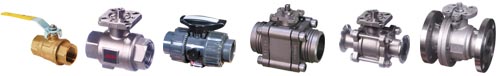
A number of 2-way ball valves are shown here. Note the variety of body materials and end connections. Valves shown without levers show the ISO 5211 mounting pad for attaching actuators directly to the valve without the need for mounting brackets.

In the CLOSED position, the side of the ball prevents flow of the fluid by sealing against the seats that it is sandwiched between. When rotated 90 degrees (quarter-turn)
to the OPEN position, the fluid is free to pass through the bore on the ball. The valve illustrated here is "Full-Port" which means that the bore in the ball is as big as the pipe's inner diameter, therefore not restricting flow at all.
Select a 2-way Ball Valve
3-way Ball Valves
3-way ball valves are basically the same as 2-way, with 3 ports instead of 2. In these valves, the ball's bore is either "L" shaped, or "T" shaped depending on the function to be performed.

As you can see here, 3-way ball valves have the same variety of body materials and end connections.

Select a 3-way Ball Valve
Butterfly Valves
Butterfly valves are similar to ball valves in that they operate by rotating an obstructor 90 degrees from open to closed position. In these valves, however, the obstructor is a thin disc that turns sideways to open. The disc is perpendicular to flow and completely obstructs the flow in the closed position, and when rotated 90 degrees, the flow travels around the thin profile of the sideways disc. These valves are commonly used as basic on/off valves, but are also suited for proportional flow control by stopping the disc at intermediate positions. When controlling processes on larger pipe sizes, weight and cost are lower on butterfly valves when compared to ball and plug valves of the same size.
Manually operated butterfly valves employ a basic lever at smaller sizes. These levers have various intermidiate positions that they "lock-in" to to ensure repeatability as well as prevent the disc from being rotated by the flow of the media. Larger size butterfly valves use a hand wheel and gearbox to ease the task of generating sufficient torque. a graduated dial on the gearbox will indicate the disc position in this case.

In the CLOSED position, the disc is perpendicular to the flow and fills the entire opening through the valve. When rotated 90 degrees (qurter-turn) to the OPEN position the fluid passes around the disc and through the valve.
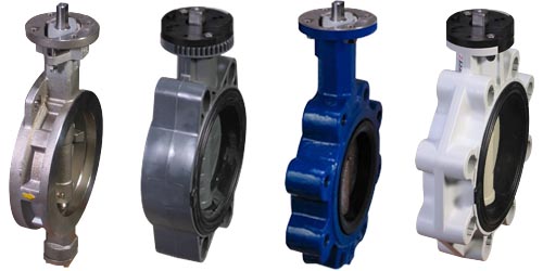
Butterfly valves also come ion a variety of materials. There are 2 main connection types shown here. The two valves on the left are wafer style and the two on the right are lugged. Both of these connection styles are for mating with flanges on the ends of the pipes.
High Performance Butterfly Valves
Resilient Seated Butterfly Valves
These valves have rigid body with a soft seat. The seat acts as both the seal between the valve and pipes, and the seal between the valve and disc.
3-way Butterfly Valves
The geometry of these valves make it impossible for them to be 3-way. When processes with large diameter pipes require a valve with 3-way functionality, an assembly of two butterfly valves on a Tee fitting is used. The two valves are synchronized via a mechanical connection. This connection can be a rod, or a chain drive. See an example of a 3-way Butterfly Valve and Tee Assembly

The 2 main connection styles, wafer flange and lug flanged, are illustrated here. Lugged style is able to install with pipe on only one side for "dead-end" service.
Select a Butterfly Valve
Plug Valves
Plug valves are practically identical to ball valves with the main differnce being the shape of the obstructor is a slightly tapered cylinder. They also operate by rotating the obstructor 90 degrees from open to closed position.
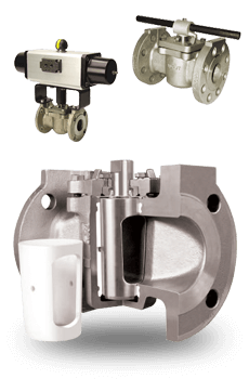
There are many advantages of plug valves over ball valves. One of the main advantages is that they can be adjusted while in use to fix stem leakage. Another advantage is the absence of cavities around the plug in which the media can become trapped. For a comprehensive white paper that details the differences between ball and plug valves click here.
Non-Lubricated Plug Valves
Sleeved Plug Valves
Select a Plug Valve
Valve Actuators
Two Types of Power: Electric and Pneumatic
Actuators require some method of being powered. The 2 main types of power used for process control valves are electric and pneumatic. There are pros and cons for each. When deciding which type to use, refer to our Actuator Decision Tree.
Compare all Valve Actuators
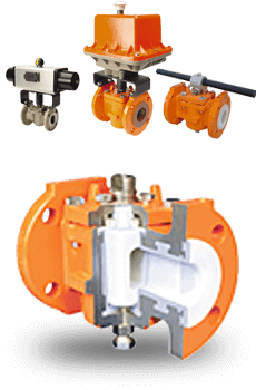
Pneumatic Actuators
Pneumatic valve actuators use air to generate rotational force in order to turn the valve stem which is attached to the ball, plug, or disc. The most common air pressures used are 60 and 80 psi. Higher air pressure will generate more torque.
There are 2 different styles of pneumatic actuators: Scotch Yoke and Rack-n-Pinion. Both of these can be either spring return or double acting. Spring return models use air in one direction and a spring in the other. This offers the benefit of a fail-safe position, that your valve will return to in the case of control air loss. Double acting models use air in both directions and remain in their current position upon loss of air.
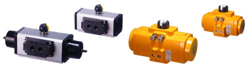
Various pneumatic valve actuators shown here. Scotch yoke on the left, rack-n-pinion on the right. Spring return in front, double acting in back.
In order to use a pneumatic actuator, you must have a method to control the supply air to the actuator. This is done using an electric solenoid valve. Well designed actuators have an industry standard NAMUR mounting pad that allows the mounting of the solenoid valve directly to the actuator. This type of mounting simply and accurately lines up the air ports of the actuator with the ports on the solenoid valve. See our NAMUR mount solenoid valves.
By themselves, these actuators are for on/off operation, meaning fully open or closed. They can be made to be modulating for proportional control by adding a positioner. These positioners can be controlled via air (pneumatic) or via electricity (electro-pneumatic). See our pneumatic actuator positioners.
Spring Return Rack-n-Pinion Actuator Operation

Note how the torque reduces from the beginning to the end of each stroke.
Double Acting Rack-n-Pinion Actuator Operation

Note how the torque is even throughout the entirety of both strokes, and is equal when comparing the two.
Spring Return Scotch Yoke Actuator Operation 
Note how the torque dips in the middle of each stroke and is a mirror image of itself when comparing the 2 strokes.
Double Acting Scotch Yoke Actuator Operation 
Note how the torque dips in the middle of each stroke and is identical to itself when comparing the 2 strokes.
Select a Pneumatic Actuator
Electric Actuators
Electric actuators are available in a variety of common voltages. They typically operate more slowly than pneumatic models. They do not normally have a fail-safe position, however they are available as an option on some models via a battery that will provide for a single actuation to the fail-safe position in the event of power loss.
An important consideration of electric actuators is the protection ratings. There are standards set by NEMA (National Electrical Manufacturers Association) for use of electrical components in different environments. For instance any actuator that is to be used outdoors, where it is exposed to weather, must meet the requirements for NEMA 4/4X to prevent the ingression of rain water. Another situation would be any environment with combustible vapors present. This would require a NEMA 7 rating which means that it would contain any sparks that may occur and prevent an explosion.
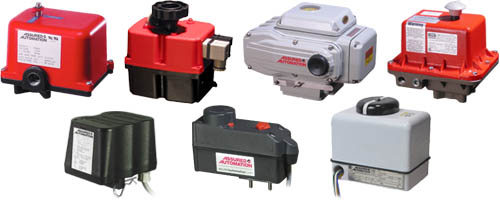
Electric valve actuators come in all shapes and sizes.
Electric actuators can be on/off or modulating. Modulating control is achieved by the addition of a circuit board inside the actuator. The modulation is controlled by an industry standard control signal input of either 4-20mA or 0-10VDC. Typically the low end (either 4mA or 0VDC) will drive the actuator to the closed position, and the high end (either 20mA or 10VDC) will drive it to the open position. Any signal in between will drive the actuator to the corresponding proportional position. This signal can be reversed on most models so that the low end is open, and the high end is closed.
Select an Electric Actuator
Need Help Selecting a Process Control Valve?

Live Chat
Live Chat
Offline
regular hours:
8:30-5:00 M-F
Eastern Standard Time

Email

Phone
 Search
 (0)
(0)


