VA Series
Materials
Body: Nickle Plated Brass
Seals: Viton, EPDM, or Buna
Connections
NPT: 3/8" to 2"
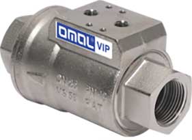
VIP Series
Materials
Body: Nickle Plated Brass
Seals: Viton, EPDM, or Buna
Connections
G (BSPP): 3/8" to 2"
VIP-EVO Series
Materials
Body: Aluminum (non-wetted)
End Conn: Ni plated Brass (wetted)
Piston: Chem. Ni plated Brass (wetted)
Seat: PTFE 15% Glass Fiber
Seals: Viton, EPDM, or Buna
Connections
NPT: 3/8" to 2"
G (BSPP): 3/8" to 2"
Angle Valves
Materials
Body: SS or Bronze
Seals: PTFE
Connections
NPT: 3/8" to 2"
Tri-Clamp: 1/2" to 2"
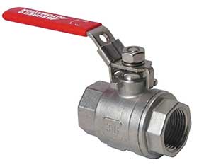
SV Series
Materials
Body: Stainless Steel
Seals: Viton or EPDM
Connections
NPT: 1/4" to 2"
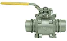
RSG Series
Materials
Body: SS or Brass
Seals: FKM
Seats: PTFE
Connections
NPT: 3/8" to 1 1/4"
SM Series
Materials
Body: Brass or Lead Free Brass
Seals: PTFE
Seats: PTFE
Connections
NPT: 1/2" to 2"
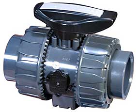
P2 Series
Materials
Body: PVC
Seals: EPDM or Viton
Seats: PTFE
Connections
NPT: 1/2" to 4"
Glue Socket: 1/2" to 4"
101 Series
Materials
Body: Nickel Plated Brass
Seals: PTFE
Seats: PTFE
Connections
NPT: 3/8" to 3"
26 Series
Materials
Body: Stainless steel
Seals: PTFE & Viton
Seats: RPTFE
Connections
NPT: 1/4" to 3"
38 Series
Materials
Body: Stainless steel
Seals: PTFE
Seats: RPTFE
Connections
NPT: 1/4" to 3"
Socket Weld: 1/4" to 3"
Tri-clamp: 1/2" to 4"
Ext. Tube Butt Weld: 1/2" to 4"
36 Series
Materials
Body: Stainless steel
Seals: PTFE
Seats: RPTFE
Connections
NPT: 1/4" to 3"
Socket Weld: 1/4" to 3"
Tri-clamp: 1/2" to 4"
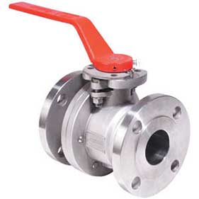
150F/300F Series
Materials
Body: Carbon or stainless steel
Seals: TFM or Graphite
Seats: TFM or 50/50
Connections
150#: 1/2" to 8"
300#: 1/2" to 8"
150F/300F Series
Materials
Body: Carbon or stainless steel
Seals: TFM or Graphite
Seats: TFM or 50/50
Connections
150#: 1/2" to 8"
300#: 1/2" to 8"
HPF Series
Materials
Body: Carbon or stainless steel
Seals: TFM or Graphite
Seats: TFM or 50/50
Connections
NPT: 1/2" to 4"
Socket Weld: 1/2" to 4"
HPF Series
Materials
Body: Carbon or stainless steel
Seals: TFM or Graphite
Seats: TFM or 50/50
Connections
NPT: 1/2" to 4"
Socket Weld: 1/2" to 4"
XP3 Series
Materials
Body: Carbon or stainless steel
Seals: TFM or Graphite
Seats: TFM or 50/50
Connections
NPT: 1/2" to 4"
Socket Weld: 1/2" to 4"
DSI-WG Series
Materials
Body: Carbon Steel (A216 WCB)
Trim: API Trim 8 (others available)
Connections
150#: 2" to 30"
300#, 600#, 900#, 1500#: Call
XLB Series
Materials
Body: PFA lined Ductile Iron
Seals: PTFE
Seats: PTFE
Connections
150#: 1/2" to 6"
V Series
Materials
Body: Carbon or Stainless Steel
Seats: PTFE, TFM, or 50/50
Seats: PTFE, TFM, or 50/50
Connections
NPT: 1/2" to 4"
150#/300#: 1/2" to 8"
Tri-Clamp: 1/2" to 4"
SM Series
Materials
Body: Brass or Lead Free Brass
Seals: PTFE
Seats: PTFE
Connections
NPT: 1/2" to 2"
30D Series
Materials
Body: Stainless Steel
Seats: PTFE
Seals: PTFE
Connections
Tri-Clamp: 1/2" to 4"
31D Series
Materials
Body: Stainless Steel
Seats: PTFE
Seals: PTFE/Viton or RPTFE
Connections
NPT: 1/4" to 3"
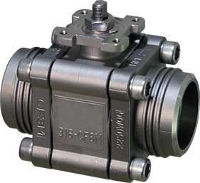
33D Series
Materials
Body: Brass
Seats: RPTFE
Seals: RPTFE/Viton
Connections
NPT: 1/4" to 2"
MPF Series
Materials
Body: Carbon or Stainless Steel
Seats: TFM
Seals: TFM
Connections
150#: 3/4" to 6"
300#: 1 1/2" to 6"
PTP Series
Materials
Body: PVC
Seats: PTFE
Seats: EPDM or Viton
Connections
NPT: 1/2" to 2"
Glue Socket: 1/2" to 2"
BFY Series
Materials
Body: 316L SS
Seats: EPDM, SIlicon, or Viton
Connections
Tri-Clamp: 1/2" to 6"
Butt Weld: 1/2" to 6"
FE Series
Materials
Body: PVC
Seats: EPDM
Connections
Wafer: 1 1/2" to 12"
FK Series
Materials
Body: GRPP
Seats: Polypropylene
Connections
Wafer: 1 1/2" to 12"
Lugged: 2 1/2" to 12"
HP Series
Materials
Body: Carbon or Stainless Steel
Seats: RPTFE
Connections
Wafer: 2" to 12"
Lugged: 2" to 12"
HPX Series
Materials
Body: Carbon or Stainless Steel
Seats: Graphite
Connections
Wafer: 3" to 48"
Lugged: 3" to 48"
ANSI class 150, 300, 600
HPX Series
Materials
Body: Carbon or Stainless Steel
Seats: Graphite
Connections
Wafer: 3" to 48"
Lugged: 3" to 48"
ANSI class 150, 300, 600
ST Series
Materials
Body: Epoxy Coated Ductile Iron
Seats: BUNA or EPDM
Connections
Wafer: 2" to 12"
Lugged: 2" to 24"
XLD Series
Materials
Body: PFA Lined Ductile Iron
Seats: Viton
Connections
Wafer: 2" to 24"
Lugged: 2" to 24"
061 Series
Materials
Body: PFA Lined Ductile Iron
Plug: PFA Lined Ductile Iron
Connections
150#: 1/2" to 4"
067 Series
Materials
Body: Stainless Steel
Seals: PTFE
Connections
150#: 1/2" to 4"
XP3 Series
Materials
Body: Stainless Steel or Carbon Steel
Seals: PTFE, RPTFE, PFA, or Special
Connections
150#: 1/2" to 12"
300#: 1/2" to 12"
GVI Series
Materials
Body: Carbon or Stainless Steel
Trim: SS, TFE, or PEEK
Connections
150#: 1/2" to 4"
300#: 1/2" to 4"
NPT: 1/2" to 2"
SW: 1/2" to 2"
GV Series
Materials
Body: Bronze or Stainless Steel
Trim: Bronze, SS, or PEEK
Connections
NPT: 1/2" to 2"
Butt Weld: 1/2" to 2"
GH Series
Materials
Body: Cast Iron
Trim: Bronze or SS
Connections
150# Flange: 2 1/2" to 8"
300# Flange: 2 1/2" to 8"
EWG Series
Materials
Body: Carbon Steel (A216 WCB)
Trim: API Trim 8 (others available)
Connections
150#: 2" to 30"
300#, 600#, 900#, 1500#: Call
DSI-WG Series
Materials
Body: Carbon Steel (A216 WCB)
Trim: API Trim 8 (others available)
Connections
150#: 2" to 30"
300#, 600#, 900#, 1500#: Call
21 Series
Materials
Body: Stainless Steel
Seats: PTFE
Seals: PTFE
Connections
NPT: 1/4" to 2"
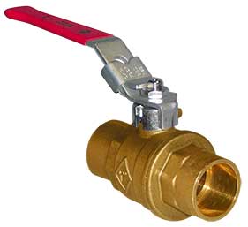
282 Series
Materials
Body: Brass
Seats: PTFE
Seals: PTFE
Connections
NPT: 1/4" to 4"
NPT (male x female): 1/4" to 1"
Solder: 1/2" to 4"
282LF Series
Materials
Body: Lead Free Brass
Seats: PTFE
Seals: PTFE
Connections
NPT: 1/2" to 2"
Manual Valves
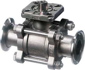
2-way Ball Valves
NPT: 1/4" to 3"
Socket Weld: 1/4" to 3"
Tri-Clamp: 1/2" to 3"
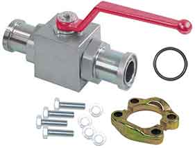
3-way Ball Valves
NPT: 1/4" to 2"
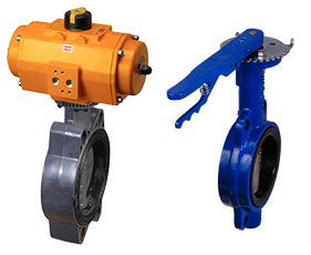
Butterfly Valves
Lugged: 2" to 8"
112LF Series
Materials
Body: Stainless Steel
Seats: PTFE
Seals: PTFE
Connections
NPT: 1/2" to 2"
282LF Series
Materials
Body: Brass
Seats: PTFE
Seals: PTFE
Connections
NPT: 1/4" to 4"
NPT (male c female): 1/4" to 1"
Solder: 1/2" to 4"
250LF Series
Materials
Body: Lead Free Brass
Seats: PTFE
Seals: PTFE
Connections
NPT: 1/2" to 2"
Manual Valves
2-way Ball Valves
NPT: 1/4" to 3"
Socket Weld: 1/4" to 3"
Tri-Clamp: 1/2" to 3"
3-way Ball Valves
NPT: 1/4" to 2"
Butterfly Valves
Lugged: 2" to 8"
TSV Series
Materials
Valve: Ball or Butterfly
Body: Carbon or Stainless Steel
Seals: Delrin®
Connections
NPT: 1/4"
SW: 1/4"
150#: 1/4"
300#: 1/4"
Lugged: 1/4"
Wafer: 1/4"
FireChek® Series
Materials
Body: Stainless Steel
Seals: Delrin®
Connections
NPT: 1/4"
ISO: 1/4"
FM Fire-Safe Valves
Materials
Body: Carbon or Stainless Steel
Seals: Graphoil
Seats: Xtreme RPTFE
Connections
NPT: 1/2" to 2"
150#/300#: 1/2" to 4"
Lug/Wafer: 3" & 4"
ESD Series
Materials
Body: Carbon or Stainless Steel
Seals: TFM or Graphite
Seats: TFM or 50/50
Connections
150#: 1/2" to 8"
300#: 1/2" to 8"
NPT: 1/2" to 4"
Socket Weld: 1/2" to 4"
ESOV Series
Materials
Body: Carbon or Stainless Steel
Seat: API Trim 8 or 12
Cover Seal: Graphite
Connections
150#: 2" to 16"
300#: 2" to 16"
150F/300F Series
Materials
Body: Carbon or Stainless Steel
Seals: TFM or Graphite
Seats: TFM or 50/50
Connections
150#: 1/2" to 8"
300#: 1/2" to 8"
FM Fire-Safe Valves
Materials
Body: Carbon or Stainless Steel
Seals: Graphoil
Seats: Xtreme RPTFE
Connections
NPT: 1/2" to 2"
150#/300#: 1/2" to 4"
Lug/Wafer: 3" & 4"
HPF Series
Materials
Body: Carbon or Stainless Steel
Seals: TFM or Graphite
Seats: TFM or 50/50
Connections
NPT: 1/2" to 4"
Socket Weld: 1/2" to 4"
HP Series
Materials
Body: Carbon or Stainless Steel
Seals: TFM or Graphite
Seats: TFM or 50/50
Connections
Wafer: 2" to 12"
Lugged: 2" to 12"
ESD Series
Materials
Body: Carbon or Stainless Steel
Seals: TFM or Graphite
Seats: TFM or 50/50
Connections
150#: 1/2" to 8"
300#: 1/2" to 8"
NPT: 1/2" to 4"
Socket Weld: 1/2" to 4"
C Series
Materials
Housing: Extruded aluminum alloy
End Caps: Powder coated die-cast aluminum
Torque
Spring Return: up to 56,500 in/lbs.
Double Acting: up to 59,000 in/lbs.
F Series
Materials
Housing: Polyurethane coated aluminum
Torque
Spring Return: up to 13,211 in/lbs.
Double Acting: up to 21,430 in/lbs.
O Series
Materials
Housing: Aluminum with corrosion resistant coating
Torque
Spring Return: up to 25,600 in/lbs.
Double Acting: up to 25,600 in/lbs.
P Series
Materials
Housing: Aluminum with corrosion resistant coating
Torque
Spring Return: up to 25,600 in/lbs.
Double Acting: up to 25,600 in/lbs.
CE Series
Materials
Housing: Ploycarbonate plastic (ABSPC)
Torque
100 in/lbs.
V4 Series
Materials
Housing: Epoxy coated aluminum
Torque
125 or 300 in/lbs.
R4 Series
Materials
Housing: Polycarbonate
Torque
300 or 600 in/lbs.
S4 Series
Materials
Housing: Anti-corrosive polyamide
Torque
up to 2,600 in/lbs.
O Series
Materials
Housing: Diecast aluminum alloy
Torque
up to 8,680 in/lbs.
B7 Series
Materials
Housing: Epoxy powder coated aluminum
Torque
up to 20,000 in/lbs.
FEX Series
Easily Retro-fits on
HPF, 150F, and 300F Ball Valves
Eliminizer Series
Air Flow
20 to 150 SCFM
Connections
NPT (female): 1/4" to 1"
Filtration
Solids: 1 micron
Water: 100% removal
Eliminizer Combo Series
Air Flow
20 to 150 SCFM
Connections
NPT (female): 1/4" to 1"
Filtration
Solids: .01 micron
Water: 100% removal
01N Series
Materials
Body: Nylon
Connections
NPT: 1"
01A Series
Materials
Body: Aluminum
Connections
NPT: 1"
DM-P Series
Materials
Body: Plastic
Connections
NPT (male): 1/4" to 1"
MAG Series
Materials
Body: Stainless Steel
Connections
NPT: 1/4" to 2"
BSPP: 1/4" to 2"
T-clamp: 1/2" to 2"
G2 Series
Materials
Body: SS, Aluminum, or Brass
Connections
NPT: 1/2" to 2"
T-clamp: 3/4" to 2 1/2"
Flange: 1" to 2"
TM Series
Materials
Body: PVC schedule 80
Connections
NPT: 1" to 4"
Glue Socket (female): 1" to 4"
Flange: 3" to 4"
WM-PT Series
Materials
Body: PVC sched. 60 or 80
Connections
Glue Socket (male): 1/2" to 4"
Insertion: 1 1/2" to 8"
WWM Series
Materials
Body: PVC sched. 60 or 80
Connections
Glue Socket (male): 1/2" to 4"
Insertion: 1 1/2" to 8"
LM Series
Materials
Body: Aluminum
Connections
NPT: 1/2"
WM Series
Materials
Body: Epoxy Coated Bronze
Connections
NPT: 1/2" to 2"
WM-NLC Series
Materials
Body: Lead Free Brass
Connections
NPT: 1/2" to 2"
WM-NLCH Series
Materials
Body: Lead Free Brass
Connections
NPT: 1/2" to 2"
D10 Series
Materials
Body: Lead Free Brass
Connections
NPT: 1/2" to 1"
Flange: 1 1/2" to 2"
WM-PC Series
Materials
Body: Fiber Reinforced Polymer
Connections
NPT: 1/2" to 1 1/2"
WM-PD Series
Materials
Body: Glass Reinforced Polyamide
Connections
NPT: 1/2" to 3/4"
Pulse Output
for Water Meters
Learn what Pulse Output is and compare the water meters available with this feature.
Accessories
for Water Meters
See all of the accessories offered for our water meters.

 Search
 (0)
(0)


 , & RSG)
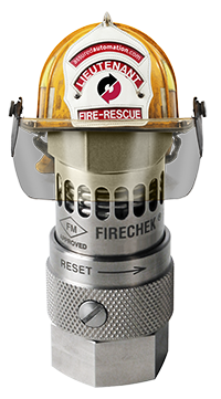 an Assured Automation